


Solar Photovoltaic (PV) Installation for DIY Camper

The following is a tutorial for how to install a solar photovoltaic (PV) system for a DIY camper, van, or RV. The examples, pictures, and videos shown are specific to the custom slide-in camper I am building for my 6ft pickup, but they should offer a guideline for anyone attempting to do a similar type of solar install. Many of the steps and components of the system may be overly complicated or unnecessary for the type of install you are performing. Follow each step and include components at your discretion. Safety, however, is NOT optional! DO NOT work with HOT wires!! All circuitry must have some sort of fault protection (fuses/breakers) and isolation capabilities.
Step 1: Sizing the System

The first step in setting up a solar photovoltaic (PV) system for a camper or RV is to calculate how much power will be drawn by all the electrical devices to be connected. Assumptions will need to be made as to how many hours per day each device will be operating (drawing power). Due to energy lost when converting from 12-volt direct current (DC) to 120-volt alternating current (AC), it is recommended to avoid using 120V AC devices wherever possible and use 12V DC devices instead.
The most important information is to determine the amps (A) that will be drawn by each device and for how many hours (h) it will operate, because battery sizes are provided in Amp-hours (Ah). It is always a good idea to overestimate the hours to be certain you will size your battery bank properly. Certain devices will require 120V AC power, however, so an inverter will still be necessary. When determining the power draw required for 120V AC devices, a good rule of thumb is to assume an 80% conversion efficiency for the inverter. The power drawn from a 120V AC device can usually be found on the power supply or on the device itself. An example is shown of where to find the wattage on the power supply and how to calculate the 12V power draw for two laptop computers.
Once the total power requirements have been determined, battery capacities can be chosen to meet those power demands (The example above shows that I would need 305 Ah per day). The sizes (wattage) of the solar panels can also be determined by calculating the Watt-hours of energy produced by the panels (assume ten hours of sun per day) then converting that into Amp-hours by dividing by 12V. A table is included with the devices and power requirements for the camper that I am building. It is recommended to setup a spreadsheet with the equations provided to make sizing the system easier.
The next step is to create a wiring diagram and determine which devices can/should be on shared circuits or have their own isolated circuit.
Step 2: Create a Wiring Diagram

The wiring diagram does not need to be made using computer software with real pictures of the devices to be connected, as in the example. The wiring diagram can be hand drawn, and words, numbers or a coding system (e.g. AC for air conditioner, or FB10 for fuse box-10A) can be used in place of pictures. It is imperative that the diagram be clearly understandable to anyone who may be working on the system.
The system consists of a few necessary components:
1. Solar Panels (connected in parallel [(+) to (+) & (-) to (-)] for 12V, or in series [(+) to (-)] for higher voltages).
2. Charge Controller (controls the volts and amps input to the batteries to prevent overcharging/damage).
3. Battery Bank (if using more than one 12V battery, connect all batteries in parallel, designating a main battery for all other connections - charge controller, inverter, and 12V circuits should be connected only to the main battery, not to the secondary batteries).
4. Kill Switches/Fuses (connected in-line to cutoff power for emergencies or to work on the system).
5. Fuse Box (used for 12V devices to prevent excessive power draw that can damage the system or other devices).
6. Inverter (converts 12V DC power to 120V AC power).
7. Electrical Devices (connected to 12V DC or 120V AC as necessary).
At a minimum, kill switches (preferably combined with a fuse) should be connected between the solar panels and the charge controller, as well as between the batteries and the primary electrical devices (fuse box and inverter). In this example, the inverter came with a fuse and has a built-in switch located on the rear of the device, so a separate kill switch is not necessary. For added safety, another kill switch could be installed between the charge controller and the batteries, allowing for complete isolation of any system components if desired. Kill switches are always to be installed on the positive voltage line connecting the components.
Shared Circuits or Isolated Circuits:
Deciding which electrical lines to put on the same circuit or which keep on their own circuit is entirely up to you. You may want to isolate electrical lines by their location (front, rear, etc), the amount of amperage, or the type of circuit (lights, water pumps, 12V outlets, etc). Devices that pull large amounts of amperage should be isolated on their own fuse. I recommend anything single device pulling more than 5 amps be placed on an isolated circuit. Devices that pull fewer amps can be combined onto shared circuits. Just make sure to put them on a fuse that exceeds the total possible amperage if all devices are powered simultaneously. For example, the 12V LED lights (of which there are 12 in total) pull 3W of power each, which means they draw 0.25A of current (3W / 12V = 0.25A). Assuming every LED is on at the same time, the total amps would be 0.25A * 12 = 3A. With this as the maximum amps drawn by all the LEDs, it is safe to put all the lights plus a small (0.25A) fan for the bathroom (totaling 3.25A) together on a 5A circuit (fuse in the fuse box).
Note: Standard fuse sizes generally consist of 5, 10, 15, and 20 amps. Be sure not to exceed the amperage capacities of each port on the fuse box, as well as the total amps for the fuse box (e.g. the fuse box I'm using is 8 ports, can handle 30A per port and 100A total). First determine how many devices will be combined on their own circuit before deciding what size (number of ports) fuse box to purchase.
Once the wiring diagram is laid out, all components are accounted for, and necessary safety devices are included, installation can begin.
Step 3: Install Wiring (disconnected)
 |
 |
 |
 |
 |
 |
 |
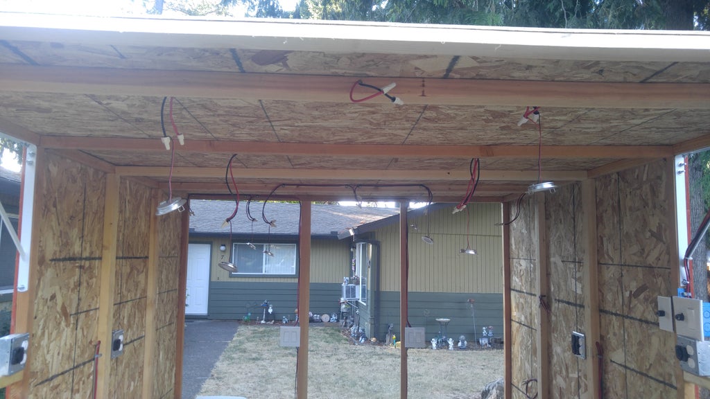 |
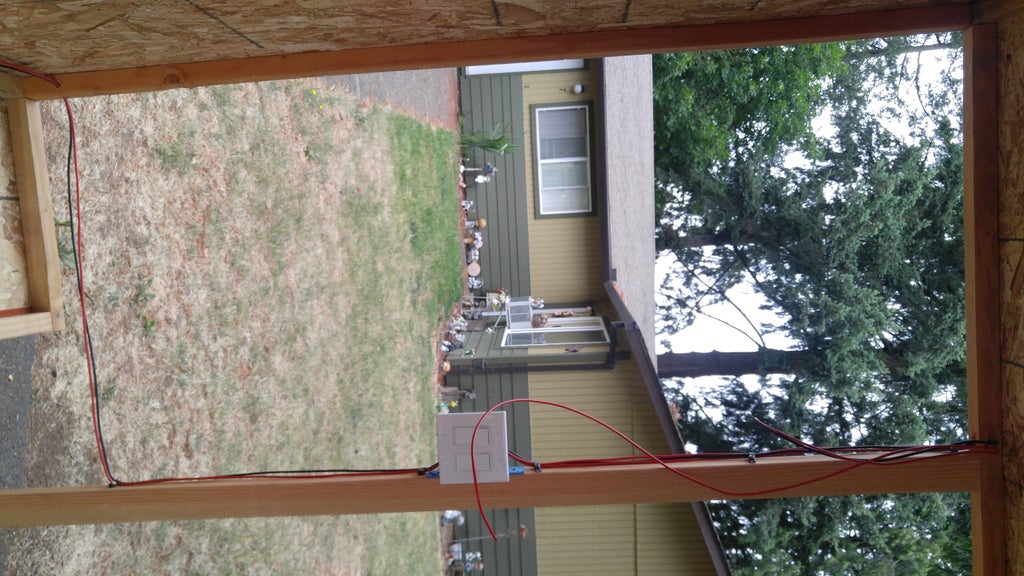
Other than installing the wires from the solar panels to the central location for the primary electrical components (charge controller, batteries, fuse box, inverter, etc.), this step may be skipped if a full wiring installation is not necessary. If installing on a fully constructed camper or RV, for example, installing wires may not even be possible. For the camper I am building from scratch, however, I wanted different outlets in certain locations of the camper. This is not necessary, though, and can be left to your preference.
For wiring between the main components (battery --> battery, battery --> 12V circuits, battery --> inverter, etc.), be sure to use a large wire (I'm using 4-gauge) that can easily handle whatever amperage is going through it.
For 12V wiring, be sure to use a wire that can handle the amperage and distance of the lines. I'm using 10-gauge, which may be a bit overkill, but it is better to be safe than sorry.
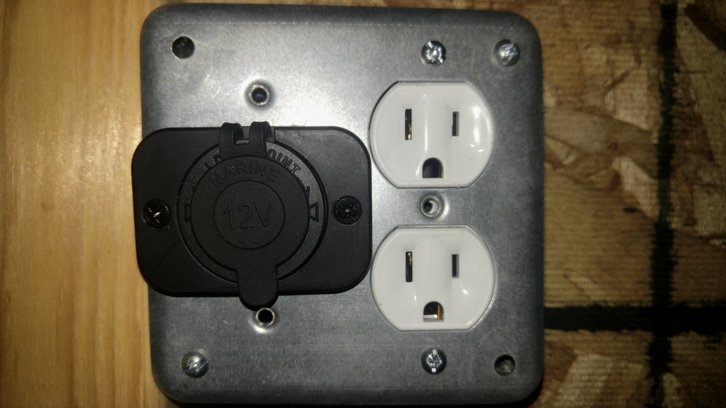
Installing wiring and outlets is an optional step. All connections can be made at the central electrical box. A power strip/surge protector can be connected to the inverter, and all 120V devices can connect to that. 12V outlets (cigarette lighter plugs) can be connected directly to the fuse box (or 12V bus if in-line fuses are included, which they were for 12V outlets I purchased).
Install all wiring, switches, and outlets. DO NOT connect any of the wires in the central electrical box or to the solar panels. Connections CAN be made at the end-use receptacles (outlets and devices) and switches for lights and devices (NOT kill switches). All unconnected wires at the end points should be capped to prevent electrocution once connected in the central electrical box.
Not every device needs its own line to be run back to the central electrical box. If the device will be on the same circuit (fuse) in the electrical box, then the lines can be split off at the nearest junction to the device's location to reduce the total length of electrical wire needed. The circuit for the LED lights discussed in the wiring diagram, for example, can be spliced off the same line. To split the lines, I cut the lines then attached a third line to them using ring terminals, a nut and a bolt with a locking washer. Be sure to insulate any exposed wire (especially for the hot line) with electrical tape or heat shrink tubing.
For 120V AC wiring, I chose to cannibalize a 50 ft. extension cord, cutting it into smaller lengths to run to each outlet, as this was the cheapest option. If cost is not a concern, however, it is recommended to use proper wiring for home electrical installations.
Step 4: Wire Outlets and Switches
 |
 |
 |
|
 |
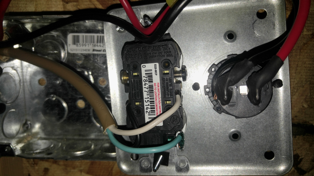
Standard 120V AC electrical wiring most commonly consists of three wires (hot, neutral, and ground). Standard wiring is: black = hot; white = neutral; green/bare wire = ground. The rear of an electrical outlet will have screw connections. Commonly, only the "hot" (usually brass color) is labeled, the opposite side (usually steel color) is the neutral connection, and ground is designated by a green screw.
For 12V DC wiring, any color wire may be used, but the standard is: red = hot; black = ground. When wiring the rear terminals of the 12V DC outlets, connect the red wire to (+) and the black wire to (-). For most of the 12V wiring, connections are made with "quick disconnect" spade terminals to allow for quickly and easily connecting or disconnecting devices and outlets. The fuse box purchased came with "quick disconnect" connections as well. For connections that would never or rarely be disconnected, like inner wall splits or ground connections, ring terminals were used.
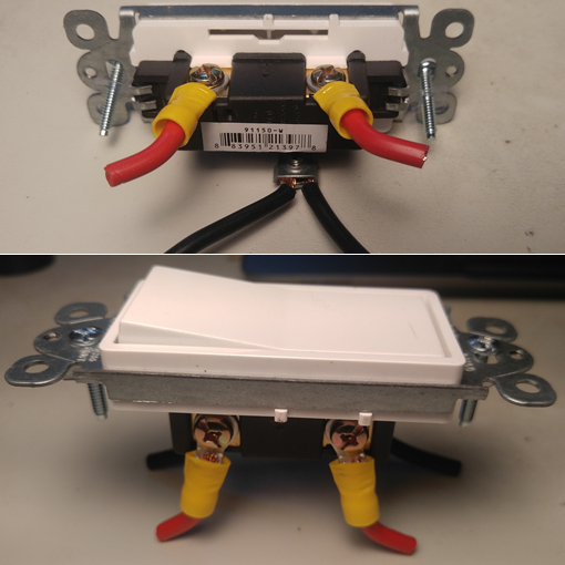
When wiring an ON/OFF switch for lights or another device, the hot wire should be cut and connected to the two adjacent screw terminals (the switch connects the two terminals in the ON position). While not 100% necessary, it is recommended to connect the ground wire to the green screw on the switch with no break (strip a small section of wire without cutting it). A standard ON/OFF switch for 120V AC power will work for a 12V circuit. A 120V AC dimmer switch, however, will not work for 12V circuits, as the resistance is too high.
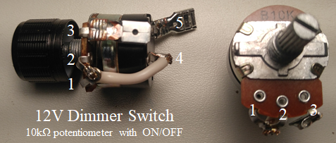
12V Dimmer Switch (*attempt at your own risk*): To dim the 12V LEDs, a 10k-ohm potentiometer (variable resistor) with ON/OFF positions was used. ***This option is NOT recommended unless you are familiar with potentiometers and how they work.*** A standard potentiometer has three terminals (1, 2, and 3), whereas the ON/OFF potentiometer has 5 terminals (the 3 standard plus 2 on the rear). The two rear terminals (4 & 5) act as a standard ON/OFF switch (connected in the ON position and disconnected in the OFF position).
1. Connect one of the rear terminals (4) directly to the center standard terminal (2).
2. Connect one end of the cut "hot" wire to the other rear terminal (5), and
3. Connect the other end of the cut "hot" wire to the standard terminal (3) that measures ~10k ohms [to the center terminal (2)] when the dial is in the OFF position.
4. The opposite terminal (1) will measure ~0 ohms in the OFF position and should be connected directly to the center terminal (2).
I soldered "quick disconnect" spade connectors onto the terminals for the "hot" wires (3 and 5).
With all the wiring in place, you can begin making connections in the central electrical box.
Step 5: Wire Connections in Central Electrical Box
***WARNING*** ***WARNING***
***ALL KILL SWITCHES MUST BE IN THE OPEN/OFF POSITIONS***
Start by wiring the lines coming from the solar panels (solar panels NOT connected) to the charge controller, making sure to install a kill switch in-line for the positive connection. Connect all wires to the charge controller, but DO NOT make the connections to the battery or solar panels yet. Again, make sure the kill switch is in the open/off position.
Install the wires from the battery bank to the inverter (for 120V AC) and the kill switch to the main fuse box (for 12V DC), but DO NOT connect the wires to the batteries. Again, make sure the kill switch is in the open/off position.
Connect all the 12V ground wires to the same ground bus. Once all the ground wires are connected, the positive wires can now be connected to the appropriate fuses. Ensure you are connecting the correct wires by labeling them during installation, or tracing them with a toner device.
Once all the 12V connections are made, begin connecting the 120V wires.
This process is much simpler, as the power inverter will handle the 120V AC load, and all outlets can be on the same circuit. First, connect all the ground (green) wires, then the neutral (white) wires, followed by the hot (black) wires. The order of connection is not extremely important when there is no power on the lines, but it is better to be in the habit of connecting ground wires first.
If using more than one battery, you can connect the batteries together at this point (creating a battery bank), but DO NOT connect the main battery to any other components (charge controller, inverter, 12V circuits, etc.). Use a large wire (I'm using 4-gauge) to connect the batteries together.
Step 6: Install and Connect Solar Panels
Install the solar panels in the desired location. I built a frame to attach the panels to instead of mounting them directly to the roof. The frame will then be attached to the roof using locks and latches, which will allow for adjusting the angle and bearing of the panels when stationary to maximize solar absorption. If this method is used, be sure to properly secure the panels before traveling again.
Cover the solar panels with a blanket (or something else) to prevent light from striking the panels and electricity from being produced.
Connect the solar panels in parallel for a 12V system:
1. Connect the ground (-) terminal wires for each panel together.
2. Connect the positive (+) terminal wires for each panel together.
3. Connect the ground (-) terminals to the appropriate wire leading to the charge controller.
4. Connect the positive (+) terminals to the appropriate wire leading to the charge controller. **Again, make sure the kill switch is in the OPEN/OFF position before making this connection.
5. Remove the cover/blanket from the panels.
For the Renogy panels used in this tutorial, MC4 connectors are pre-installed, so no wire is exposed.
Step 7: Make Final Connections & Power Up the System
It is time to make the final connections and power up the system. Before making connections, ensure that all kill switches are in the OPEN/OFF position.
Connect the charge controller, power inverter, and 12V bus wires to the battery bank. (If using more than one battery, designate a main battery to connect to other components. Do not connect one battery to the charge controller and another to the inverter or fuse box)
1. Connect the ground (-) wire from the charge controller, inverter, and 12V ground bus to the ground (-) terminal of the main battery.
2. Connect the positive (+) wire from the charge controller, inverter, and 12V bus/fuse box to the positive (+) terminal of the main battery. Close the kill switch between the charge controller and the battery bank (if installed).
3. Close the kill switch between the solar panels and the charge controller.
4. Close the kill switch between the battery bank and the 12V bus or fuse box.
5. Flip (close) the switch on the rear of the inverter to the ON position.
6. Test outlets, switches, and other devices to ensure they work properly. **If something is not working properly, open all kill switches before troubleshooting** Try retracing lines or check for punctures/breaks where wires attach to studs. Make sure all connections are fastened securely and making good contact.
Congratulations!!
You now have a fully installed and operational solar photovoltaic system for your camper, van, or RV!